Please Rate Us on this post

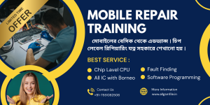
Learn Mobile Repairing Course
Join the most complete Bengali Mobile Repairing Course covering hardware, software, IC reballing, EMMC/UFS programming, dead mobile boot repair, and oscilloscope reading. Perfect for beginners to advanced learners. Learn in Bengali at Baharu, Joynagar, South 24 Parganas, Kolkata. Contact: +91-7551082506.
Complete Bengali Mobile Repairing Course In Kolkata
📞 Contact for Admission:
Email: trueword360@gmail.com
Phone: +91-7551082506
Apply Now All Light IC Basics | Working, Pinout & Testing Guide for Free

Details Of Light IC Section (Short Summary)
This section covers everything a technician needs to diagnose and repair mobile LCD backlight issues: what the Light IC does, which pins to check, how to test safely (cool/hot tests), typical faulty components (coil, diode, capacitors, IC), and step-by-step repair actions. Use the Cool Testing Report for offline checks and the Hot Testing Report for live measurements. Always start with power rail verification (VPH), then passive components, then control signals (PWM/EN/SCL/SDA), and replace the IC only after ruling out simpler faults.
Common Faults
No backlight while image is visible (dark screen that becomes visible under torch).
Dim or uneven brightness (one side brighter than the other).
Flickering or auto-dimming (brightness changes randomly).
Backlight turns on then quickly turns off (auto-disable / protection).
No PWM or communication (IC not responding; shows as hardware/software handshake failure).
Main Function
Boost battery voltage to required LED anode voltage (typically 15–50V) for backlight.
Receive PWM/CABC/EN signals to switch and control brightness.
Monitor LED currents via feedback pins (K1/K2) and protect against short/open.
Interface with PMIC/CPU via SCL/SDA (I²C) on complex ICs for configuration.
Provide stable, filtered output using diode and capacitors to prevent flicker.
Important Pins of IC
VPH (Power In) — main supply (≈ 3.7–4.2V battery rail).
Boost / SW / Coil pin — switching node connected to boost inductor.
Anode / LED Out — high-voltage output to LED strings (15–50V).
PWM / CABC / EN — control/enable lines (commonly 1.8V logic).
Feedback (K1/K2) & GND — current sense and ground reference for protection.
Important Pictures on This Topic
Picture 1

Picture 2

Schematic View

Video Guide
👉 In short:
Cool Testing Report
Hot Testing Report
Cool Testing Report (Multimeter / Static Checks) Light IC
Check VPH present (4.0–4.3V) before powering — if missing, trace PMIC.
Diode/coil continuity: measure coil + diode for open/short; replace if open.
Multimeter resistance (GR) checks on pins: expect low-ohm to GND where appropriate and specific GR ranges for diode/feedback (use your device baseline).
Check capacitor for short (cap = no GR / open = high resistance).
Inspect connector pins and LCD flex for corrosion or broken traces.
Hot Testing Report (Powered & Live Checks) Light IC
VPH under load: stable near battery voltage (≈ 3.7–4.2V).
Boost output: 15–50V present on anode when enabled and PWM present.
PWM: ~1.8V logic pulses when LCD is active — check with meter or scope.
LED lines: equal current across LED chains (no single-line overload).
Temperature: IC and coil should warm slightly — large heat indicates short/overload.
Details Of This Section
Step-by-Step Guide — How to Repair (with Common Faults) Light IC
Tools needed: multimeter, oscilloscope (recommended for PWM/I²C), hot air or soldering iron, microscope, fine SMD parts (coil, diode, caps), current-limited PSU, tweezers, flux.
Visual & Basic Check
Inspect board, LCD flex, connectors for corrosion, cold joints, or damage.
Remove battery before any soldering.
Measure VPH (Cool)
With multimeter, confirm VPH pin/bus ≈ 3.7–4.2V. If missing → trace to PMIC/fuse.
Check Passive Components (Cool)
Test boost coil for continuity. Replace if open.
Test diode (Schottky) for short or open using diode mode.
Check large electrolytic/tantalum caps for short/open; replace suspicious caps.
Cool Resistance / GR Tests
Use diode/resistance checks between the IC pins and ground/other pins. Note abnormal open/short compared to a working unit or expected range.
Power On (Hot) — Use Current-Limited PSU
Connect supply with current limit (0.5–1A). Monitor for shorts.
If current shoots up immediately — likely shorted diode/cap/IC.
Check Boost Output (Hot)
If VPH present and PWM present, measure anode voltage to LED chain: should be ~15–50V depending on LED string. If no boost → look at coil/diode/IC switching.
Check PWM / EN / CABC (Hot)
With scope/meter, verify PWM pulses (1.8V logic) when display active. If PWM missing → trace to CPU/PMIC or LCD enable signals.
For I²C-enabled ICs, verify SCL/SDA lines activity with scope; if no comms, IC won’t initialize.
Feedback & LED Lines
Measure feedback pins (K1/K2). If feedback senses open LED string, IC will turn off. Repair LED string (connector or screen issue) or correct shorted LED.
Component Replacement
Replace faulty coil/diode/cap first. Re-test. If still no backlight but passive parts ok and PWM present → suspect Light IC.
Replace IC only if confident and have correct replacement. Prefer to replace with known-good part.
Post Repair Testing
Reboot and perform hot tests again: VPH, Boost, PWM, LED voltage and current. Check for overheating and stable brightness.
Software/Driver Checks
On devices where IC uses I²C, ensure software/firmware didn’t disable backlight. Reflash/restore settings only after hardware verified.
Final Validation
- Test with LCD connected, test multiple brightness levels, and run for several minutes to confirm no flicker or thermal issues.